PULSE and DIGITAL CIRCUITS UNIT WISE Important Questions and Answers :-
UNIT 1
1. a)What is meant by linear wave shaping? Give some examples of linear wave shaping circuits.
b) Obtain the response of high pass RC circuit for a ramp input wave form.
Show that the output of a differentiator circuit is derivative of the input.
2. (a) A Current pulse of amplitude I and width tP is applied to a parallel RC combination, (C input side). Plot to scale the waveforms of the current iC for the cases
i. tP< RC ii. tP= RC iii. tP> RC
(b) Compare RC low pass circuit with RC high pass circuit.
3. (a) The limited ramp is applied to an RC differentiator. Draw to scale, the output wave form for the following cases i. T=RC, ii. T=0.4RC, iii. T=10RC.
(b) Derive the expression for the response of RC low pass circuit to which ramp input is applied
4. (a) Verify V2= (V/2)(e2x−1)/(e2x+1) = (V/2) tanhx for a symmetrical squarewave applied to a low pass RC circuit.
(b) Derive the expression for percentage tilt(P) of a square wave output of RC high pass circuit.
5. (a) Derive the expression for rise time of integrating circuit and prove that it is proportional to time constant and inversely proportional to upper 3 dB frequency.
(b) Explain the operation of RC low pass circuit for exponential input is applied.
6. Write Short notes on:
(a) Diode switching times (b) Switching characteristics of transistors
(b) Write a short note on switching times of a transistor.
i. Rise time. ii. Delay time. iii. Turn-on time. iv. Storage time. v. Fall time. vi. Turn-off time.
UNIT-II
1. (a) Give the circuits of different types of shunt clippers and explain their operation with the help of their transfer characteristics.
2.(a) Draw the basic circuit diagram of negative peak clamper circuit and explain its operation.
b) Draw the basic circuit diagram of positive peak clamper circuit and explain its operation
3. (a) Explain transfer characteristics of the emitter coupled clipper and derive the necessary equations.
4. (a) What is meant by clipping in wave shaping?(b) Classify different types of clipper circuits. Give their circuits and explain their operation with the aid of transfer characteristics.
5. (a) Draw the circuit diagram of a double clipping circuit using diodes to clip at two different reference levels and draw its transfer characteristic and explain its operation.
6. a) Explain how clipping at two independent levels can be achieved.
b) Explain the operation of a diode comparator with a ramp input signal.
UNIT-III
1. a) What are different types of multivibrators? Explain the stable state of a multivibrator.
b) Sketch the circuit diagram of Schmitt trigger and explain its operation.
2. (a) What is a direct connected binary circuit? Explain the direct connected binary
with the help of a circuit diagram
3. Design a Monostable circuit that produces a pulse width of 10 m sec. Assume
hfe=30, VCE(sat)=0.3V, VBEsat=0.7V Ic=5mA, Vcc=6V. VBB=1.5V, Q1 ON and Q2 OFF
4. (a) Draw the circuit diagram of self-bias with symmetrical triggering using diodes.
Explain the working of the same.
(b) Compare between triggering at base and collectors.
UNIT-IV
1. (a) Draw and explain the circuit diagram of a diode AND gate for positive logic.
(b) Derive the output equation for a diode OR gate for positive logic.
2. (a) What are the basic logic gates which perform almost all the operations in
Digital communication systems.
(b) Give some applications of logic gates.
(c) Define a positive and negative logic systems.
(d) Draw a pulse train representing a 11010111 in a synchronous positive logic
digital system.
3. (a) Draw and explain the circuit diagram of integrated positive DTL NAND gate
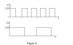
(b) Consider a two input positive logic diode OR and AND gates. Sketch the
output waveform. Shown in figure 8
4. a) Draw the circuit diagram of CMOS NAND gate and explain its operation.
b) Compare the performance of TTL and MOSFET logic gates.
5. a) Compare the performance of TTL and ECL logic gates with respect to power dissipation,
noise margin, cost and propagation delay time.
b) Draw the circuit, symbol and truth-table of a NAND ,NOR,XOR Gates
6. a) What is the difference between bipolar logic family and unipolar logic family? Explain.
b) What do you understand by the terms fan-in and fan-out? Draw an RTL circuit.
UNIT-V
1. a) Define the following terms:
i) Time base ii) Sweep voltage
iii) Sweep speed error iv) Displacement error
2. (a) What is relaxation oscillator? Name some negative resistance devices used as
relaxation oscillators and give its applications.
(b) Explain the principle of working of exponential sweep circuit with neat circuit
diagram and also derive the equations for slope , transmission and displacement error.
3. (a) Draw and clearly indicate the sweep time and flyback time on the typical
waveform of a time base voltage.
(b) Derive the relation between the slope, transmission and displacement errors
(c) Explain how UJT is used for sweep circuit
4. (a) Draw the circuit of a constant current sweep circuit and derive the expression
for sweep voltage.
5. (a) List the methods of generating time-base waveforms.
b) Explain the basic principles of Miller and Bootstrap time base generator?
c) What is meant by time base generator? Explain the expositional sweep circuit.
UNIT-VI
1. (a) What do you mean by synchronization ?
(b) What is the condition to be met for pulse synchronization?
(c) Compare sine wave synchronization with pulse synchronization?
2. (a) Explain with some example how a negative resistance devices used as relaxation oscillator which is used for synchronization?
(b) Explain how the symmetrical signals are used to synchronize a sweep circuit?
3. (a) Explain how a sinusoidal oscillator can be used as a frequency divider.
(b) Write short notes on i. Phase delay and ii. Phase jitters
4. (a) How astable multivibrator can be synchronized? Illustrate with waveforms.
5. (a) With the help of a neat diagram, explain the working of four-diode sampling gate.
b) Distinguish between unidirectional and bi-directional sampling gates.